SPECIFICATIONS
Overall Dimensions
Imperial |
Metric |
Series |
|
Wing span |
88ft 6in 93ft 6in |
26.98m 28.50m |
200/300/400 475/500 |
Wing chord at root
|
16ft 5in 16ft 9.5in |
5.01m 5.11m |
All versions except 475/500 (late prod) |
Wing chord at tip |
5ft 3.5in 5ft 5in |
1.61m 1.65m |
All versions except 475/500 (late prod) |
Wing aspect ratio |
8.0 8.5 8.65 |
|
200/300/400 500 (early prod) 475/500 (late prod) |
Sweepback at quarter chord |
20 degrees |
|
All versions |
Overall length |
93ft 6in 107ft 0in |
28.50m 32.61m |
200/300/400/475 500 |
Fuselage length |
83ft 10in 97ft 4in |
25.55m 29.67m |
200/300/400/475 500 |
Max fuselage width/depth |
11ft 2in |
3.40m |
All versions |
Overall height |
24ft 6in |
7.47m |
All versions |
Tailplane span |
29ft 6in |
8.99m |
All versions |
Ground clearance to fuselage |
2ft 7.5in |
0.80m |
All versions |
Wheel track |
14ft 3in |
4.34m |
All versions |
Wheel base |
33ft 1in 33ft 0in 41ft 4in |
10.08m 10.06m 12.60m |
200/300/400 475 500 |
Overall turning radius measured to outer wing tip |
51ft 6in 56ft 0in |
15.70m 17.07m |
200/300/400/475 500 |
Forward passenger doorHeight Width Height to sill |
5ft 8in 2ft 8in 7ft 0in |
1.73m 0.82m 2.13m |
All versions All versions All versions |
Ventral entranceHeight Width Height to sill |
6ft 0in 2ft 4in 7ft 0in |
1.83m 0.71m 2.13m |
All versions All versions All versions |
Galley service doorHeight Width Height to sill |
4ft 0in 2ft 3in 7ft 0in |
1.22m 0.69m 2.13m |
All versions All versions All versions |
Overwing emergency exitsHeight Width |
3ft 0in 1ft 8in |
0.91m 0.51m |
All versions All versions |
Main deck freight doorHeight Width Height to sill |
6ft 1in 10ft 0in 7ft 0in |
1.85m 3.05m 2.13m |
400/475 400/475 400/475 |
Underfloor frt door (Fwd)Height (projected) Width Height to sill |
2ft 7in 3ft 0in 3ft 7in |
0.79m 0.91m 1.09m |
All versions All versions All versions |
Underfloor frt door (Rear)Height (projected) Width Height to sill |
2ft 2in 3ft 0in 4ft 3in |
0.66m 0.91m 1.30m |
All versions All versions All versions |
Internal Dimensions
|
Imperial |
Metric |
Series |
Cabin length (including flight deck) |
56ft 10in 70ft 4in |
17.31m 21.44m |
200/300/400/475 500 |
Max cabin width |
10ft 4in |
3.16m |
All versions |
Max cabin height |
6ft 6in |
1.98m |
All versions |
Max floor width |
9ft 6in |
2.98m |
All versions |
Floor area (approx)
|
506ft² 665ft² |
47.00m² 61.78m² |
200/300/400/475 500 |
Forward freight hold Height Width Length
Volume |
3ft 0in 7ft 5in 17ft 11in 22ft 10in 354ft³ 451ft³ |
0.91m 2.26m 2.46m 6.96m 10.02m³ 12.77m³ |
All versions All versions 200/300/400/475 500 200/300/400/475 500 |
Rear freight hold Height Width Length
Volume |
3ft 0in 7ft 5in 11ft 6in 10ft 0in 15ft 0in 180ft³ 156ft³ 236ft³ |
0.91m 2.26m 3.51m 3.06m 4.59m 5.09m³ 4.42m³ 6.68m³ |
All versions All versions 200/300/400 475 500 200/300/400 475 500 |
External Areas
|
Imperial |
Metric |
Series |
Gross wing area
|
980ft² 1031ft² |
91.04m² 95.78m² |
200/300/400 475/500 |
Ailerons (total) |
30.8ft² |
2.86m² |
All versions |
Flaps (total) |
175.6ft² |
16.30m² |
All versions |
Spoilers (total) |
24.8ft² |
2.30m² |
300/400/475/500 |
Vertical tail surface (total) |
117.4ft² |
10.90m² |
All versions |
Rudder (including tab) |
32.8ft² |
3.05m² |
All versions |
Horizontal tail surface (total) |
257ft² |
23.9m² |
All versions |
Elevators (including tab) |
70.4ft² |
6.55m² |
All versions |
Weights & Loadings
|
Imperial |
Metric |
Series |
Typical Operating Weight Empty (varies with customer fit) |
46,405lb 48,722lb 50,822lb 51,822lb 51,731lb 54,582lb |
21,049kg 22,098kg 23,050kg 23,505kg 23,464kg 24,758kg |
200 300 400 NAL 400 475 500 |
Maximum Payload |
17,595lb 20,025lb 21,269lb 26,418lb |
7,981kg 9,083kg 9,647kg 11,983kg |
200 300/400 475 500 |
Maximum Take-off Weight |
79,000lb 88,500lb 98,500lb 104,500lb |
35,833kg 40,142kg 44,678kg 47,400kg |
200 300/400 475 500 |
Maximum Landing Weight |
71,000lb 78,000lb 87,000lb |
32,204kg 35,380kg 39,462kg |
200 300/400 475/500 |
Maximum Zero Fuel Weight (varies between customers – typical figure shown) |
64,000lb 71,000lb 68,500lb 73,000lb 81,000lb |
29,030kg 32,204kg 31,070kg 33,112kg 36,741kg |
200 300/400 NAL 400 475 500 |
Maximum Wing Loading |
78.3lb/ft² 88.8lb/ft² 89.2lb/ft² 96.7lb/ft² |
382.0kg/m² 433.6kg/m² 435.5kg/m² 472.0kg/m² |
200 300/400 475 500 |
Maximum Power Loading |
3.82lb/lb st 3.96lb/lb st 4.16lb/lb st |
390.1kg/kN 400.3kg/kN 424.7kg/kN |
300/400 475 500 |
The Maximum Ramp Weight figure for each model is 500lb (226.8kg) greater than the quoted MTOW figure shown above.
Performance
|
|
Series |
Max level cruising speed at 21,000ft (6,400) TAS |
548mph (475kt, 882km/h) 541mph (470kt, 871km/h) |
200/300/400 475/500 |
Fuel economical cruising speed at 25,000ft (7,620m) TAS |
507mph (440kt, 815km/h) 461mph (400kt, 742km/h) |
200/300/400 475/500 |
Max never exceed diving speed (structural) EAS at sea level |
460mph (399kt, 740km/h) 472mph (410kt, 760km/h) |
200 300/400/475/500 |
Stalling speed (take-off flap setting) EAS |
125mph (109kt, 201km/h) 131mph (114kt, 211km/h) 114mph (99kt, 184km/h) 121mph (105kt, 195km/h) |
200 300/400 475 500 |
Rate of climb at sea level at 345mph (300kt, 555km/h) EAS |
2,500ft/min (762m/min) 2,580ft/min (786m/min) 2,480ft/min (756m/min) 2,280ft/min (695m/min) |
200 300/400 475 500 |
Maximum cruise altitude |
35,000ft (10,670m) 37,000ft (11,285m) 40,000ft (12,200m) |
200 300/400/475/500 NAL 400 |
Still air range with max Fuel, ISA, with reserves for 230 miles (200nm, 370km) diversion and 45 minutes hold |
2,130 miles (3,430km) 2,250 miles (3,620km) 2,300 miles (3,700km) 2,165 miles (3,484km) |
200* 300/400 475 500 |
Still air range with capacity payload, ISA, reserves as above |
875 miles (1,140km) 1,430 miles (2,300km) 1,865 miles (3,000km) 1,705 miles (2,744km) |
200 300/400 475 500
|
Ferry range with zero payload, ISA, reserves as above |
2,617 miles (4,215km) 2,477 miles (3,988km) 2,430 miles (3,912km) 2,339 miles (3,766km) 2,206 miles (3,552km) 3,950 miles (6,357km) |
200* 300 400 475 500 NAL 400 |
Still air range with max standard fuel, ten passengers and 45 minutes reserve |
3,753 miles (6,040km) |
NAL 400 |
Still air range with max optional fuel, eight passengers and 45 minutes reserve |
3,950 miles (6,357km) |
NAL 400 |
Take-off run at sea level, ISA |
6,500ft (1,981m) 7,500ft (2,286m) 7,450ft (2,270m) 5,500ft (1,676m) 6,500ft (1,981m) |
200 300 400 475 500 |
Balanced take-off to 35ft (10.70m) at sea level, ISA |
6,850ft (2,088m) 8,000ft (2,438m) 7,800ft (2,377m) 5,900ft (1,798m) 7,300ft (2,225m) |
200 300 400 475 500 |
Landing distance (BCAR) at sea level, ISA, at max landing weight |
4,720ft (1,439m) |
475 |
Flap operating speedsTake-off setting |
253mph,(220kt, 408km/h) 276mph,(240kt, 445km/h) |
200 300/400/500 |
Approach setting |
207mph,(180kt, 334km/h) 220mph,(191kt, 354km/h) 222mph,(193kt, 358km/h) |
200 300/400/475 500 |
Landing setting |
190mph,(165kt, 306km/h) 207mph,(180kt, 334km/h) 211mph,(183kt, 339km/h) |
200 300/400 475/500 |
Landing gear operating speedsApproach setting |
253mph,(220kt, 408km/h) 265mph,(230kt, 427km/h) |
200 All other |
* With optional centre tank
Integral wing tanks on all versions had a capacity of 2,235 Imperial Gallons ( 10,160 litres).
A centre tank of 850 Imperial Gallons (3,864 litres) was standard on all versions except the Series 200 where it was an option.
Additional extra tankage could be accommodated as a further option in the rear of the forward hold amounting to 350 imperial gallons (1,591 litres) or 700 imperial gallons (3,182 litres).
The National Aircraft Leasing modified VIP aircraft were offered with either 1,015 imperial gallons (4,618 litres) or 1,332 imperial gallons (6,056 litres) once again fitted in the rear of the forward hold.
One-Eleven Series 200
The initial production version was the Series 200, powered by 46.3 KN Rolls-Royce RB163 Spey 506-14 turbofans. The aircraft (G-ASHG cn 004) first flew from Hurn on the 20 August 1963. First delivery went to Braniff Airways (N1543 cn 017) on 11 March 1965, while British United Airways received their first aircraft (G-ASJJ cn 014) on 6 April 1965. Other customers for this version were Braniff Airways, Mohawk Airlines, Aer Lingus, and Aloha Airlines. Three aircraft were also supplied new as corporate jets to Helmut Horten GmbH and Tenneco Inc, while two others were delivered to the Royal Australian Air Force. The last aircraft (N503T cn 183) was delivered to Tenneco on the 8 July 1969. A total of 58 Series 200 aircraft were built.
One-Eleven Series 300
In May 1963 BAC announced two new versions of the One-Eleven; the Series 300 and Series 400, both of which offered more powerful Spey 511-14s of 50.7 kN thrust, fitted into lengthened nacelles. Although dimensions were the same as the Series 200, the Series 300 offered longer range by virtue of an additional centre section fuel tank and a higher maximum take-off weight. The aircraft (G-ATPJ cn 033) first flew from Weybridge on the 20 May 1966. First delivery went to British Eagle International Airways (G-ATPJ cn 033) on 8 June 1966 while Laker Airways received their first aircraft on the 25 February 1967. The Series 300 was only ordered by three customers, British Eagle, Laker and Kuwait Airways who cancelled their order. The last aircraft was delivered to Laker (G-AVYZ cn 133) on the 11 April 1968. A total of 9 Series 300 aircraft were built.
One-Eleven Series 400
The Series 400 was originally configured with a maximum take-off weight of 36060 kgs, which was lower than the Series 300’s 40000 kgs due to US restrictions on the gross weight for two-crew operation. With the easing of the restrictions, the maximum take-off weights of US-operated Series 400s were brought into line with those of the Series 300 through adoption of 300’s additional centre-section fuel tank and the two models became effectively indistinguishable. The aircraft (G-ASYD cn 053) first flew from Hurn on the 13 July 1965. First delivery went to American Airlines (N5015 cn 055) on 23 December 1965. Other Series 400 customers included Austral, Autair, Bahamas Airways, Bavaria Flug, Channel Airways, Lacsa, Philippine Airlines, Quebecair, Tarom and VASP. One aircraft was supplied new as a corporate jet to Engelhard Industries, and two were delivered as transports to the Brazilian Air Force. The last Series 400 was delivered to Bavaria Flug (D-ANNO cn 160) on the 22 December 1970. A total of 70 Series 400 aircraft were built. Many former airline aircraft were subsequently converted to executive configuration and in particular 16 former American Airlines aircraft were converted by the Dee Howard Company at San Antonio for National Aircraft Leasing Inc. it is these aircraft that make up the great majority of the still active Series 400 fleet.
One-Eleven Series 475
The Series 475 was the last UK-built version of the One-Eleven, conceived to bring improved field performance to the One-Eleven range, in addition to the capability to operate from unprepared runways. These goals were achieved by combining the standard length fuselage of the Series 400 with the increased wingspan and more powerful engines of the Series 500 and a new undercarriage fitted with larger low pressure tyres. The Series 475’s maximum take-off weight was 44678 kg. The Aircraft (G-ASYD cn 053) first flew from Hurn on the 27 August 1970. The first delivery went to Faucett of Peru (OB-R-953 cn 239) on 23 July 1971. Further airline orders for the Series 475 came from Air Malawi, Air Pacific and Tarom. Three were fitted out as corporate jets and three more were supplied to the Air Force of the Sultanate of Oman, all of which were eventually fitted with a large cargo door (3.05m x 1.85m) on the port forward fuselage. The last two Series 475 (G-BLHD cn 260 and G-BLDH cn 262) were delivered to McAlpine Aviation on the 9 July 1984 A total of 13 Series 475 aircraft were built.
One-Eleven Series 500
The Series 500 was launched on the strength of an order placed on the 27th January 1967 by British European Airways. This version had the fuselage extended by 13ft 6in (4.11m) by the insertion of two plugs. This allowed for four more seat rows to be installed and therefore increased passenger capacity by twenty. Overwing emergency exits had to be doubled to four. Underfloor hold volume was increased. Various structural changes were also required and higher rated Speys were fitted. This gave the aircraft a maximum take-off weight of 47400 kg. The aircraft (G-ASYD cn 053) first flew from Hurn on the 30 June 1967. First delivery (G-AVMJ cn 138) went to British European Airways on the 29 August 1968. Other Series 500 customers included British United Airways, Caledonian Airways, Panair / Paninternational, Aviateca, Bahamas Airways, Court Line, Sadia / Transbrasil, ALA / Austral, British Midland Airways, Germanair, Tarom, Philippine Airlines, Bavaria, Phoenix Airways, Lacsa, Cyprus Airways and Britsh Airways. The last delivery went to Tarom (YR-BCO cn 272) on the 12 Mar 1982 and was the last ever airliner to be constructed at Hurn! A total of 87 Series 500 aircraft were built.
Rombac One-Eleven Series 560
An agreement for the licenced production of the One-Eleven at the Romanian Government aircraft (IRMA) factory in Baneasa, Romania on was signed 9 June 1979. As the first step towards the transfer of One-Eleven production, BAC produced two Series 525 passenger aircraft and a single windowless freighter Series 485 which were supplied to CNIAR as training models. A further 22 One-Elevens were then to be supplied in kit form from the UK and assembled locally with gradually increasing Romanian content. The first Rombac One-Eleven, (YR-BRA cn 401) a series 561RC was rolled out at Baneasa on 27 August 1982, and flew for the first time on 18 September 1982. Plans for the production of 80 One-Elevens in the country were however curtailed by political and social unrest and in the end only 9 Series 561s were produced between September 1982 and April 1989. The first aircraft was delivered to Tarom on 29 December 1982. The Romanian carrier took delivery of all but two of the aircraft produced, with the remaining two going to Romavia, the last of which (YR-BRI cn 409) was delivered on 1 January 1993. Two further aircraft were partially completed when production was abandoned and scrapped.
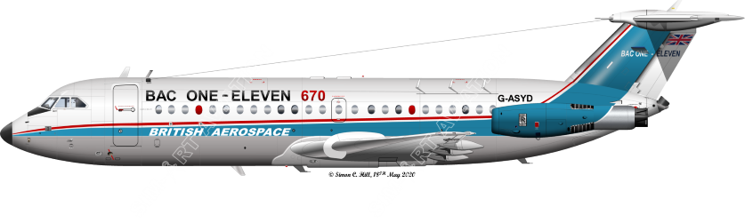
One-Eleven Series 670
A plan to supply a Series 475 derivative, the Series 670, as a YS-11 replacement to Japanese carriers resulted in one aircraft (G-ASYD cn 053) being developed and flown from Hurn on the 13 September 1977 as such, but hopes of a significant sales break through were ultimately frustrated, despite major improvements in performance, due to the Japanese authorities introducing more stringent regulatory requirements.
Projected developments not proceeded with
One-Eleven Series 600
This was a proposal to further develop the Series 500 with an additional fuselage extension, additional wing area and increased power with first deliveries to customers in the summer of 1972. Initial details were announced in September 1968. The engines proposed were a development of the Spey Mk.512-14DW with an aft fan installed immediately behind the engine thrust reverse unit. To accommodate this fan entailed the re-alignment of the power unit in relation to the fuselage and some re-design of the nacelle and the fuselage/nacelle stub fairing. The fan would have been free running with a by-pass ratio of 3 : 1 resulting in an overall by-pass ratio of 5.7 : 1. The new engines would have had a sea level static thrust output of 19,370 lbs. The water injection system would have been retained. The fuselage was extended by inserting two plugs of 13ft 4in forward of the wing and 2ft 2in aft of the wing. The rear over-wing emergency exits were deleted while the forward over-wing exit was moved forward 1ft 11.5in. Further Type one emergency exits were added between the wing and the engines with the starboard door acting as a service door as well. The aft bulkhead of the main undercarriage bay was moved rearwards to accommodate wheels and tyres of increased size while an additional cargo door was fitted forward of the wing. The wing area was increased by 174 sq ft to 1,205 sq ft by deleting the 500 Series wing tip extension and by moving the 500 Series wing 5ft outboard on an extended centre section torque-box increasing the overall wing span by 5ft. A new flap section was added to the extended centre section. The tailplane area was increased by 58 sq ft to 316 sq ft while the fin area was increased by 30 sq ft which was achieved by the addition 2ft to its height and 1 ft to the chord at the leading edge. The tail bullet was deleted leaving the whole unit looking somewhat similar to that of the DC-9. The main landing gear was modified to give a longer stroke to the oleo units and to fit 44 x 13 – 20 wheels and tyres with larger wheel brakes. Where possible, 500 Series systems were retained with modifications for the increased sizes and volumes as required. The forward passenger entry door and airstairs together with the rear ventral airstairs were retained. A third toilet was added immediately aft of the forward entry door. Various cabin layouts were proposed. These were high capacity layout of 136 seats at 29/32in pitch, 119 single class seats at 34in pitch and a two class 14 first class seats at 38in pitch and 91 tourist class seats at 34in pitch.
In January 1978 a new version of the Series 600 (with customer number 601) was promoted and offered to British Airways. This version was a much less modified version of the Series 500 than earlier proposed. It retained the standard fuselage, fin and tailplane dimensions of the Series 500. The wing was also largely unchanged and incorporated the new leading edge of the late production Series 500s and also utilised the leading edge cuff developed for the Series 670. Revised flap settings were also incorporated. With these changes an improvement of 7% would have been achieved in the take-off lift coefficient over the earlier Series.510ED giving improved airfield performance. Automatic deployment of the lift dumpers on touch down was proposed together with an improved Hytrol 111A anti-skid system in an effort to reduce the pilot workload. In the event of a go-around, the selection of increased power would lead to automatic retraction of the lift dumpers. However, the main changes came with the engine both in efficiency and noise reduction. The original Rolls-Royce Spey Mk.514-14 would have been retained but with re-engineered high temperature components for improved reliability and longer life using RB211 advanced technology. Improved HP1 turbine blades with revised attachment and shroud, increased chord nozzle guide vanes in a relocated position for better cooling and redesigned flame tubes for greater combustion efficiency would have led to improvements in climb performance and single engine ceiling. The silencing system would have had an acoustically-lined jet pipe with an eight lobe nozzle and an ejector cowl. The ejector cowl was designed to move for and aft. In the noise reduction mode at take-off and landing the cowl would have been moved aft to the point of maximum noise attenuation which would expose the thrust reverser cascades. At other times the cowl would have been moved forward to reduce drag and improve efficiency. It was anticipated that a 60% reduction in noise nuisance would have come from these changes. The use of water injection would no longer be employed with these changes. An optional 350 imperial gallon fuel tank located in the rear of the forward under floor hold was also proposed. This would have given the aircraft a 200 nautical miles increase in range with a maximum payload. The new tank would have been isolated from the hold by a new bulkhead and would have reduced the forward hold capacity to 313 cubic feet. By utilising light weight materials developed for Concorde a weight saving of 795 pounds was achieved in the cabin. Newly sculptured roof panels, deeply sculptured sidewall panels and fully enclosed overhead bins were also proposed. All these changes would have led to an increase in take-off and landing weights and in maximum payload range by almost 500 nautical miles over the Series 510EDs while compatibility with the earlier version already on strength would further increase efficiency.
One-Eleven Series 700
This was a further development of the Series 500 and was announced in November 1973 and would have entered service in early 1977. The engine employed in this version would have been the Rolls-Royce RB163-67B, later named Spey Mk.606 with a sea level static thrust of 16,900 lbs. This was a development of the Spey 512 and was mounted in a similar way to that of the original Spey engine. This engine replaced the five-stage L.P. compressor with a single stage fan and a three stage I.P. compressor on the same shaft. In order to drive the new L.P. system a third L.P. turbine stage was added utilising knowledge gained from RB-211 technology. The existing 12 stage Mk.512 H.P. system was retained but with advanced turbine cooling technology. No water injection system was employed. The engine was expected to have noise levels 5 EPNdB below FAR Part 36 requirements and 7 EPNdB below ICAO Annex 16levels when operated at aircraft maximum take-off weights and to have vastly improved fuel consumption rates over its previous form. This aircraft had an extended fuselage but less than in the Series 600. The forward plug in this case was 8ft 4in in length while the rear one was 3ft 8in. Emergency exits were as for the Series 600 above. However, the ventral entrance was now made optional while in the standard form the rear entrance was via the new door between the wing and the engines. Once again, the original forward doors and the airstairs were retained. This version retained the standard Series 500 wing but strengthened to cope with the increased weights with minor changes to the flaps, flap carriages and tracks. The fin retained the tail bullet of the earlier Series 500 aircraft. New wheels, tyres (41 x 15 – 18) and brakes were to be fitted to a new landing gear with increased stroke over that of the Series 500. Changes to the air system were expected to be confined to an increase in the size of the heat exchangers and to the cold air units. All tourist seating capacity was set at 119 at 33/34in pitch, 129 at 30in pitch or 134 with only two galley units rather than four. Three cabin crew seats were to be fitted. In February 1978 the Weybridge Project Office announced what appeared to be a development of the Series 700 but powered by Rolls-Royce RB432 engines. Other changes over the Series 700 included the fin area being increased by 40sq ft and an extended rudder with increased area. This extended the overall length of the aircraft by 2ft 8in. Other changes from the Series 500 seem to be very similar to the Series 700 above. This version was not allocated a new Series number.
One-Eleven Series 800
The final version proposed an even further stretch and employing the CFM56 Turbofan of 22,000 lbs thrust and was announced in March 1975. The two fuselage plugs of this version entailed a forward one of 24ft 2in and a rear one of 8ft 4in. The cabin layouts proposed were 144 seats at 33/34in pitch or 161 at 30in pitch while four cabin crew seats were planned. Three galleys and three toilets were planned. Due to the increased passenger complement, eight emergency exits were planned comprising the two forward doors, two rear doors and reverting to the four overwing emergency exits of the Series 500. The tailplane and fin were extended while a new wing was fitted with increased area and span. A second forward cargo door was fitted in the new fuselage plug.
Various projected versions compared with Series 500.
Series |
500 |
600 |
700 |
800 |
* |
Wing span |
93ft 6in |
98ft 6in |
93ft 6in |
103ft 6in |
93ft 6in |
Overall length |
107ft 0in |
124ft 2in |
119ft 0in |
142ft 0in |
121ft 8in |
Overall height |
24ft 6in |
27ft 0in |
24ft 6in |
25ft 9.5in |
27ft 6in |
Gross wing area |
1,031sq ft |
1,205sq ft |
1,031sq ft |
|
1,031sq ft |
Wheel base |
41ft 5in |
54ft 8in |
49ft 8in |
|
49ft 8in |
Wheel track |
14ft 3in |
15ft 7in |
14ft 3in |
|
14ft 3in |
Fuselage length |
97ft 4in |
117ft 0in |
110ft 2in |
|
110ft 2in |
Tailplane span |
29ft 6in |
40ft 2in |
29ft 6in |
|
29ft 6in |
Hold volume |
687cu ft |
815cu ft |
790cu ft |
1,075cu ft |
790cu ft |
MTOW |
104,500lb |
122,500lb |
117,000lb |
140,000lb |
115,000lb |
MLW |
87,000lb |
112,500lb |
100,000lb |
124,000lb |
100,000lb |
Max seating |
119 |
136 |
134 |
161 |
134 |
Engine thrust |
12,550lb |
19,730lb |
16,900lb |
22,000lb |
17,550lb |
Maximum payload range |
1,480nm |
1,220nm |
1,300nm |
1,825nm |
1,000nm |
Ferry range |
1,915nm |
1,900nm |
2,240nm |
|
2,050nm |
* Series 700 with Rolls-Royce RB432 engines.